Many people share .pcb files without attaching instructions on how to use it. Yet it isn’t evident for everyone which program a .pcb file can be edited, converted or printed with. On this page, we try to provide assistance for handling .pcb files.
2 filename extension(s) found in our database.
.pcb - Microsoft PowerPoint Data
The PCB other files are related to Microsoft PowerPoint. PCB file is a Microsoft PowerPoint Data. PowerPoint stores all the changes that you make to its menus and toolbars in a PCB file.
- Application:
- Microsoft PowerPoint
- Category:
- Other files
- Mime-type:
- application/mspowerpoint
- Magic:
- - / -
- Aliases:
- -
- Microsoft PowerPoint Data related extensions:
- .accda
- Microsoft Access Add-in
- .glk
- Microsoft Office 2007 Groove Synchronization Shortcut
- .act
- Microsoft Office Assistant Actor
- .acp
- Microsoft Office Assistant Preview
- .tgk
- Terragen License Key
- .tgp
- Terragen Plugin
How to Open PCB File Types with Altium Designer’s PCB Viewer Check out the Altium Designer PCB viewer free download-It’s the best option for accessing PCB layouts in the EDA file format. The viewer takes all formats within the output files, the container for schematics, layouts, and manufacturing files.
- Right-click on any PCB file and then click 'Open with' 'Choose another app'. Now select another program and check the box 'Always use this app to open.PCB files'. Update your software that should actually open or Protel Printed Circuit Board Files.
- PCB file is a SmartCAM Custom Control Panel File. SmartCAM is a suite of Computer-Aided Manufacturing and CAD/CAM software applications that uses toolpath modeling to assist CNC machinists in creating computer-numerically controlled (CNC) programs that direct CNC machine tools.
.pcb - SmartCAM Custom Control Panel File
The PCB data files are related to SmartCAM. PCB file is a SmartCAM Custom Control Panel File. SmartCAM is a suite of Computer-Aided Manufacturing and CAD/CAM software applications that uses toolpath modeling to assist CNC machinists in creating computer-numerically controlled (CNC) programs that direct CNC machine tools.
- Application:
- SmartCAM
- Category:
- Data files
- Mime-type:
- application/octet-stream
- Magic:
- - / -
- Aliases:
- -
- SmartCAM Custom Control Panel File related extensions:
- .cgt
- SmartCAM Code Generation Template
- .jof
- SmartCAM Job Operations File
- .mcl
- SmartCAM Macro File
- .pm5
- SmartCAM Process Model File
- .set
- SmartCAM Connection Settings File
- .smf
- SmartCAM Manufacture File
Naturally, other applications may also use the .pcb file extension. Even harmful programs can create .pcb files. Be especially cautious with .pcb files coming from an unknown source!
Can't open a .pcb file?
When you double-click a file to open it, Windows examines the filename extension. If Windows recognizes the filename extension, it opens the file in the program that is associated with that filename extension. When Windows does not recognize a filename extension, you receive the following message:
Windows can't open this file:
example.pcb
To open this file, Windows needs to know what program you want to use to open it. Windows can go online to look it up automatically, or you can manually select one from a list of programs that are installed on your computer.
To avoid this error, you need to set the file association correctly.
Open Pcb File Ppt
- Open Control Panel > Control Panel Home > Default Programs > Set Associations.
- Select a file type in the list and click Change Program.
The .pcb file extension is often given incorrectly!
According to the searches on our site, these misspellings were the most common in the past year:
cb, cpb, lcb, ocb, pb, pbc, pc, pcf, pcg, pch, pcn, pcv, pdb, pfb, psb
Is it possible that the filename extension is misspelled?
Similar file extensions in our database:
- .pch
- Visual Studio Precompiled Header
- .psb
- Navicat Backup File
- .pcf
- Calyx Point Point Data
- .ocb
- Origin Code Builder Object
- .pdb
- TealPaint Image Database
- .psb
- PowerDivX Subtitle
Operating systems
DataTypes.net currently supports the following operating systems:
Windows XP/Vista, Windows 7/8, Windows 10, CentOS, Debian GNU/Linux, Ubuntu Linux, FreeBSD, Mac OS X, iOS, Android
If you find the information on this page useful, please feel free to link to this page.

If you have useful information about the .pcb file format, then write to us!
Please help us by rating this page below.
CircuitMaker is not just a free EDA software tool from Altium, it’s also a community of creative people and design content, working together to invent circuits and electronics products for a better future.
Get inspired
About circuitmaker
For turning great ideas into real products, you need design tools that won’t limit your imagination or hold you back. CircuitMaker has all the power you need to design high quality schematics and Printed Circuit Boards, with no artificial limits on layer counts or board area. Best of all it’s free.
Read Morefind & rate great design content
The CircuitMaker community is where you will find great reference designs, and be able to promote and rate other projects in the community.
You can even set up teams for collaborative design efforts.
WHAT MEMBERS ARE SAYING
Eli Hughes
Wavenumber LLC.

CircuitMaker is the 1st free PCB tool I have encountered that has features of a professional design tool. A tool that is backed by people who know EDA means that we can finally have something for those of us who want to get things done without being obstructed by complicated installation, a horrible user interface or a mess of a library system. Couple this with that fact that making is also about collaborating and sharing. The folks at CircuitMaker have unique vision about creating a platform, not just a barebones tool for those who aspire to be “mad engineers”.
Roberto Lo Giacco
Professional Engineer
Finally some fresh air in the EDA market: a modern interface with some really pro capabilities and no serious limitation. This is the tool any electronics maker was waiting for and it is community focused.
Nicholas Rabault
The Poppy Project
Poppy is an open-source platform for the creation, use and sharing of interactive 3D printed robots. We love CircuitMaker because it offers the possibility of our community to contribute easily. We can promote our board model by sharing a simple link to a release. Users can produce themselves our design directly or by forking it to adapt it to their needs. Mechanical integration is a really important factor in robotics so the 3D modeling in CircuitMaker enables that.
Design the next
great electronic product
POWERFUL ECAD FOR OPEN SOURCE HARDWARE

We think you deserve better design tools, made specifically for you, to turn great ideas into reality. That’s why we’ve created CircuitMaker. Besides being a collaborative community for electronic design content, CircuitMaker is Schematic & PCB design software, built upon Altium Designer technology. With a streamlined interface and powerful engine to boot, you’ll never have to worry about your software holding you back. This is a free design tool unlike anything you’ve seen before.

UNLIMITED & FREE
Typically, free EDA software is poorly developed, or has restrictions on design size that render it useless for any real project. Not CircuitMaker - you get the full power of 16 signal + 16 plane layers, and no restrictions to the PCB dimensions. You can even make money with your designs, because there’s no “non-commercial” clause!
MASSIVE, RICH COMPONENT LIBRARY
CirucitMaker is built on a community library with hundreds of thousands of components - all backed by the awesome Octopart database. Placing components in CircuitMaker designs is as easy as searching by manufacturer part number or by design parameters. You can also add your own custom parts and mechanical components too.
SHARE & COLLABORATE
You can create projects with teams in the CircuitMaker Community, and allow other community members to work with you on the design. Harness the power of teams to get projects done faster! Released designs can be forked and then modified so you can build new designs with different features without having to start from scratch every time.
NATIVE 3D™
Altium Native 3D™ technology means that when you’re in the PCB editor, just hit the 3 key and you can immediately see the PCB layout in full 3D. It will also show any component clearance violations and you’ll even know what the overlap distances are, so you can get your designs right - and to fit the box - the first time.
ONE-CLICK MANUFACTURING
Once you have finished your design, you can release the project to the community. From there you can download the gerbers and send them off to any PCB manufacturer. But even easier than that, we’ve partnered with select manufacturers to provide a one-click manufacture button that can directly send your board for quoting - either bare board prototype or full PCB fabrication and assembly, at the best possible price. It’s up to you!
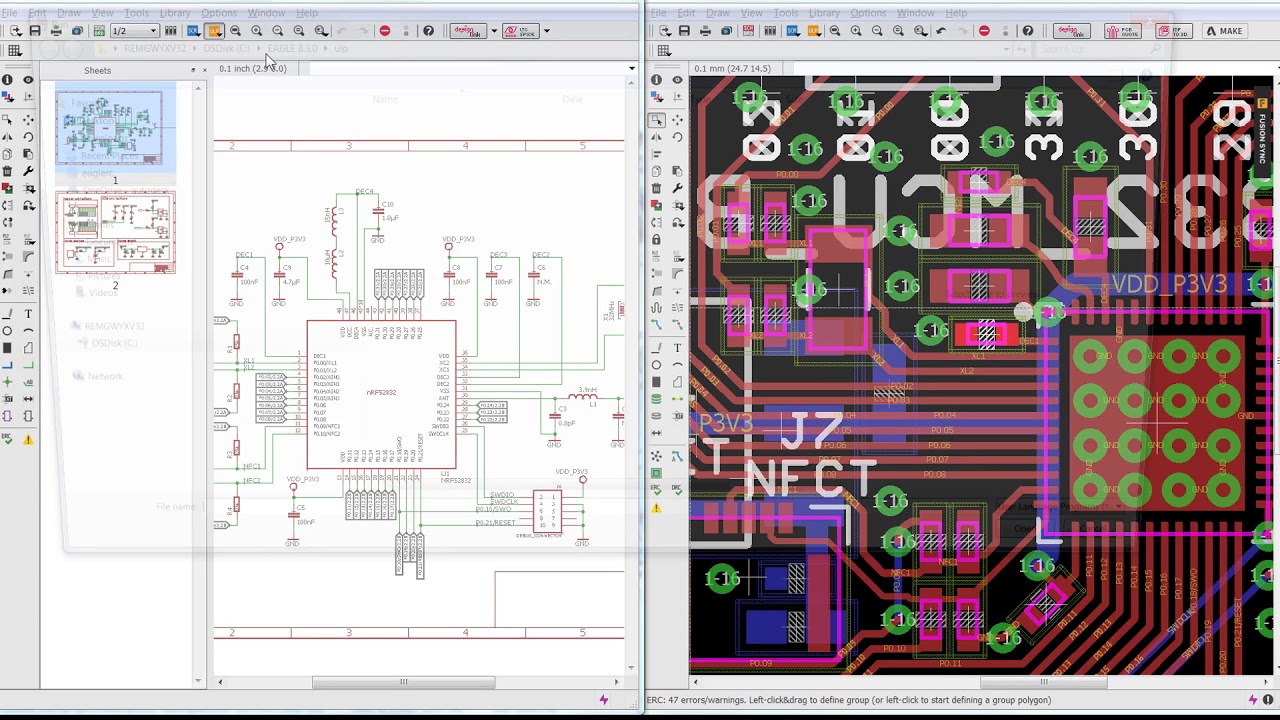
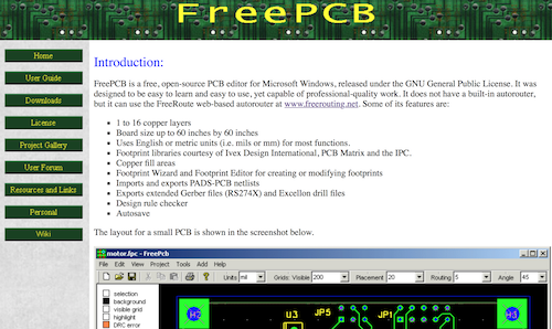
Free Software To Open .pcb File
PUSH-N-SHOVE ROUTING
For a tool we’re giving away for free, we did not hold back on the push and shove routing capabilities! The interactive routing modes include obstacle avoidance, hug, hug-n-push, and obstacle ignore. The push modes will push other trace and vias, as well as hop-over. You can even route differential pairs and interactively add accordions to nets that need that extra length for signal delays.
MULTI-SHEET SCHEMATIC EDITOR
CircuitMaker uses the same easy-to-use and great looking schematic editor Altium is known for. You can even do complex multi-sheet designs, and use hierarchical design blocks, and generate SmartPDF™ outputs from your project.
TOPOLOGICAL AUTOROUTER
The Situs™ topological autorouter works in concert with your design rules to help you get the board done fast. With BGA and SMT fanout, parallel memory, hug, and via optimization, it’s easy to use Situs to get working results really fast. You can also interactively route multi-nets or single nets, or use manual routing with auto-complete.
DRC/DFM VALIDATED OUTPUTS
When you’re ready to turn your design into a real board, CircuitMaker will generate industry standard CAM outputs. You can choose Gerber and NC Drill, or ODB++, or both. IPC test point reports and all other necessary outputs for professional manufacturing can be generated as well, and all this through a succinct release process that ensures your board passes design rules checks for DFM and assembly.
IMPORT DESIGNS FROM OTHER TOOLS
CircuitMaker comes with a huge set of importers, including OrCAD™, PCAD®, PADS®, EAGLE™, Protel and more - so starting your project from a manufacturer reference design is easy. The importers support both PCB and Schematic documents.
